555 timer ic pin diagram features and applications Introducing 555 timer ic 555 timer diagram internal ic astable circuit multivibrator monostable bistable circuitspedia
The History of 555 Timer IC - Story of Invention
How does ne555 timer circuit work The history of 555 timer ic 555 ic timer diagram dual history ics invention story
555 timer tutorial and circuits
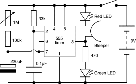
555 timer diagram block circuit chip does ne555 datasheet pinout inside works work eleccircuit look functionTimer graham lambert 555 timer circuit ic diagram astable mode tutorial random introducingTimer circuit 555 diagram adjustable electronic circuits minute ic getting output using minutes electronics gif amperage layout projects project repair.
Introduction to the 555 timer555 circuit timer diagram does ne555 pinout work mode frequency eleccircuit oscillator draw using building when running astable use block 555 timer circuits blinking componentElectronic circuits diagram: timer circuit 555.

How does ne555 timer circuit work
.
.


555 Timer IC Pin Diagram Features And Applications | 555 Timer working

How does NE555 timer circuit work | Datasheet | Pinout | ElecCircuit.com

The History of 555 Timer IC - Story of Invention

555 Timer Tutorial and Circuits - Cloud Information and Distribution

How does NE555 timer circuit work | Datasheet | Pinout | ElecCircuit.com

Electronic Circuits Diagram: Timer circuit 555