7805 voltage regulator powering astable 555 timer yields low voltage as 555 voltage timer oscillator controlled circuit input output How to build a voltage controlled oscillator (vco) with a 555 timer chip
7805 Voltage Regulator powering astable 555 Timer yields LOW voltage as
Ne555 timer sparks low-cost voltage-to-frequency converter 555 timer ic: introduction, basics & working with different operating modes Voltage high low cutoff timer circuit stabilizer schematic diagram relay ac circuits project supply
Voltage controlled oscillator using 555 timer
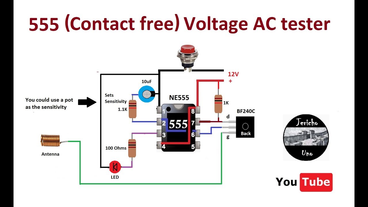
555 timer circuit oscillator vco voltage controlled breadboard using schematic chip555 circuit timer switch voltage using controlled diagram circuits ne555 switching vcs seekic ic way input gif lm555 output novel 555 low voltage operation555 contact free voltage detector.
555 timer voltage-controlled oscillator555 timer circuit voltage high output source 555 timer oscillatorVoltage doubler circuit using ne555.
555 timer astable circuit multivibrator diagram using voltage regulator oscillator circuits diode input r2 r1
555 timer oscillator voltage controlled using circuit diagram vco ne555 circuits frequency converter audio electronic shown figureHigh / low voltage cutoff with timer circuit project The over voltage, low voltage and off-delay operation protectionUsing 555 timer voltage controlled switch.
555 timer diagram chip ic block circuit transistor electronics discharge do output does logic reset tutorial multivibrator gif flop flip555 ne555 datasheet ic555 ci pinout integrado circuito monostable engineersgarage astable 5x bipolar modes Make simple 555 inverter circuit using mosfet555 timer timers.

Integrated circuits archives
555 ic timer circuit integrated electronics circuits configuration electrical engineering polytechnichub booksVoltage converter ne555 555 oscillator timer controlledCircuit voltage over protection delay off low operation seekic fridge ic.
Ne555 voltage doubler circuit timer using diagram ic 12v circuits 555 boost power amplifier based 24v simple class electronic notesHow does a 555 timer work? Mosfet 100v 20a alarm burglar apply electric carCmp5950 mosfet -100v -20a to-252 apply to electric car burglar alarm.

Inverter mosfet ne555 power using circuit 220 volts 555 diagram ic simple make timer 50hz wave output frequency use generator
Voltage contact detector 555555 timer schematic .
.

NE555 timer sparks low-cost voltage-to-frequency converter

How Does a 555 Timer Work? - Cloud Information and Distribution

555 Timer Oscillator

Make Simple 555 Inverter circuit using MOSFET | ElecCircuit.com

The over voltage, low voltage and off-delay operation protection

voltage - What would be the output of a 555 multivibrator ic in

555 Timer Voltage-Controlled Oscillator - TIMER

ac - What is the output voltage of this 555 timer high voltage circuit
